 Arduino
 Arduino OLED Display Complete Tutorial: SSD1306 I2C Wiring, Drawing and Real-time Sensor Data Display (2026)
Why You Need to Learn to Use OLED Displays
In embedded development, adding a small screen to your project can solve 80% of debugging pain points. You no longer need to print data via serial port, open serial monitor repeatedly - sensor readings can be displayed directly on the screen, clear at a glance.
And SSD1306 is the most popular OLED screen driver chip in the Arduino ecosystem, without exception. Its advantages are obvious:
| Specification | SSD1306 OLED |
|---|---|
| Resolution | 128×64 or 128×32 |
| Size | 0.96 inches (mainstream) |
| Communication Protocol | I2C or SPI |
| Operating Voltage | 3.3V-5V (compatible with Arduino) |
| Power Consumption | About 20mA |
| Price | ¥8-15 |
Hardware List
| Component | Model | Quantity | Estimated Price |
|---|---|---|---|
| Arduino Development Board | Uno/Nano/Mega all work | 1 | ¥15-25 |
| OLED Display | 0.96” SSD1306 I2C version | 1 | ¥8-15 |
| Breadboard | 400 holes | 1 | ¥5-8 |
| Jumper Wires | Male-to-female | 4 pieces | ¥2 |
Total ¥30-50.
I2C Wiring Method
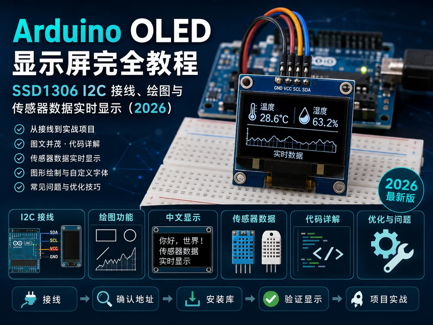
SSD1306 OLED uses I2C communication and only needs 4 wires:
Arduino UNO/Nano         SSD1306 OLED
-------------            ------------
5V (or 3.3V) ────────── VCC
GND        ────────────── GND
A4 (SDA)   ────────────── SDA
A5 (SCL)   ────────────── SCL
Arduino Mega:
SDA → Pin 20
SCL → Pin 21
Arduino Nano:
SDA → A4
SCL → A5
ESP32 (if you use ESP32 to drive OLED):
SDA → GPIO21 (default)
SCL → GPIO22 (default)Note: Most SSD1306 modules have built-in pull-up resistors, no need to add external 4.7kΩ pull-up resistors. If the screen doesn’t work, then consider adding pull-ups.
I2C Address Confirmation
SSD1306’s I2C address is usually 0x3C or 0x3D. If you’re not sure, run this scanning script:
#include <Wire.h>

void setup() {
  Serial.begin(9600);
  Wire.begin();

  Serial.println("I2C address scanning...");
  for (byte addr = 1; addr < 127; addr++) {
    Wire.beginTransmission(addr);
    if (Wire.endTransmission() == 0) {
      Serial.print("Found device address: 0x");
      Serial.println(addr, HEX);
    }
  }
  Serial.println("Scan complete");
}

void loop() {}
Environment Configuration
Install Arduino Libraries
In Arduino IDE: Tools → Manage Libraries, install the following two libraries:
- Adafruit SSD1306 — OLED screen driver
- Adafruit GFX Library — Graphics drawing base library
Verify Screen Works
Test with official example first:
File → Examples → Adafruit SSD1306 → ssd1306_128x64_i2c
After uploading, you should see the Adafruit logo and a series of graphic demonstrations appear on the screen.
If the screen doesn’t light up, check:
- Wiring is correct (SDA/SCL not reversed)
- I2C address is correct (0x3C vs 0x3D)
- Confirm in code:
#define SCREEN_ADDRESS 0x3C
Core Code Detailed Explanation
Initialization and Basic Settings
#include <Wire.h>
#include <Adafruit_GFX.h>
#include <Adafruit_SSD1306.h>

#define SCREEN_WIDTH 128
#define SCREEN_HEIGHT 64
#define SCREEN_ADDRESS 0x3C

Adafruit_SSD1306 display(SCREEN_WIDTH, SCREEN_HEIGHT, &Wire, -1);

void setup() {
  Serial.begin(9600);

  // Initialize OLED
  if (!display.begin(SSD1306_SWITCHCAPVCC, SCREEN_ADDRESS)) {
    Serial.println("SSD1306 initialization failed!");
    for (;;); // Stuck here
  }

  display.clearDisplay();       // Clear screen
  display.setTextSize(1);       // Font size 1 (default 6×8 pixels)
  display.setTextColor(SSD1306_WHITE);  // White text
  display.setCursor(0, 0);     // Cursor position (x=0, y=0)
  display.println("Hello!");
  display.display();            // Refresh screen (must call)
}

void loop() {}
Key API Description:
| Function | Purpose |
|---|---|
display.begin() | Initialize screen |
display.clearDisplay() | Clear display buffer |
display.display() | Refresh buffer content to screen |
display.setTextSize(n) | Set font size (n=1,2,3…) |
display.setCursor(x,y) | Set text start position |
display.println(text) | Output text (auto wrap to next line) |
display.print(text) | Output text (no wrap) |
Important: All drawing operations (text, graphics) first write to the memory buffer, only calling display.display() will actually refresh to the screen. This avoids flickering caused by frequent refreshes.
Display Temperature and Humidity Sensor Data
After connecting DHT22 sensor (refer to ESP32 Temperature and Humidity Monitoring Tutorial), use the following code to display data on OLED:
#include <Wire.h>
#include <Adafruit_GFX.h>
#include <Adafruit_SSD1306.h>
#include <DHT.h>

#define SCREEN_WIDTH 128
#define SCREEN_HEIGHT 64
#define SCREEN_ADDRESS 0x3C
#define DHTPIN 2
#define DHTTYPE DHT22

Adafruit_SSD1306 display(SCREEN_WIDTH, SCREEN_HEIGHT, &Wire, -1);
DHT dht(DHTPIN, DHTTYPE);

void setup() {
  Serial.begin(9600);

  if (!display.begin(SSD1306_SWITCHCAPVCC, SCREEN_ADDRESS)) {
    for (;;);
  }

  dht.begin();
  display.clearDisplay();
  display.setTextSize(1);
  display.setTextColor(SSD1306_WHITE);
  display.setCursor(0, 0);
  display.println("DHT22 + OLED");
  display.println("System starting...");
  display.display();
  delay(2000);
}

void loop() {
  float temp = dht.readTemperature();
  float hum = dht.readHumidity();

  if (isnan(temp) || isnan(hum)) {
    return;
  }

  // Clear screen and redraw
  display.clearDisplay();

  // Title
  display.setTextSize(1);
  display.setCursor(0, 0);
  display.println("== DHT22 Monitor ==");
  display.drawLine(0, 10, 128, 10, SSD1306_WHITE);

  // Temperature (large font)
  display.setTextSize(2);
  display.setCursor(0, 16);
  display.print(temp, 1);
  display.setTextSize(1);
  display.print(" C");

  // Humidity (large font)
  display.setTextSize(2);
  display.setCursor(0, 40);
  display.print(hum, 1);
  display.setTextSize(1);
  display.print(" %");

  // Refresh screen
  display.display();

  delay(2000); // Refresh every 2 seconds
}
Drawing Graphics
SSD1306 supports basic graphics like points, lines, circles, rectangles:
// Draw point
display.drawPixel(x, y, SSD1306_WHITE);

// Draw line
display.drawLine(x0, y0, x1, y1, SSD1306_WHITE);

// Draw rectangle (hollow)
display.drawRect(x, y, width, height, SSD1306_WHITE);

// Draw rectangle (filled)
display.fillRect(x, y, width, height, SSD1306_WHITE);

// Draw circle (hollow)
display.drawCircle(cx, cy, radius, SSD1306_WHITE);

// Draw circle (filled)
display.fillCircle(cx, cy, radius, SSD1306_WHITE);

// Draw rounded rectangle
display.drawRoundRect(x, y, w, h, cornerRadius, SSD1306_WHITE);

// Draw triangle
display.drawTriangle(x0, y0, x1, y1, x2, y2, SSD1306_WHITE);

// Draw progress bar
void drawProgressBar(int x, int y, int w, int h, int percent) {
  display.drawRect(x, y, w, h, SSD1306_WHITE);
  int fillW = map(percent, 0, 100, 0, w - 2);
  display.fillRect(x + 1, y + 1, fillW, h - 2, SSD1306_WHITE);
}

// Draw simple chart (line chart)
void drawLineChart(int x, int y, int w, int h, int* data, int len, int maxVal) {
  display.drawRect(x, y, w, h, SSD1306_WHITE);
  for (int i = 0; i < len - 1 && i < w; i++) {
    int y1 = y + h - map(data[i], 0, maxVal, 0, h);
    int y2 = y + h - map(data[i+1], 0, maxVal, 0, h);
    display.drawLine(x + i, y1, x + i + 1, y2, SSD1306_WHITE);
  }
}
Custom Chinese Character Display
By default, Adafruit GFX library only supports ASCII characters. If you need to display Chinese, there are several approaches:
Approach 1: Font Library Extraction Method (recommended, no external Flash needed)
- Use PCtoLCD2002 or online font extraction tools to generate font data
- Store font data in Arduino code array
- Use
display.drawBitmap()to draw
// "温" character 16×16 font (example)
static const uint8_t PROGMEM font_wen[] = {
  0x00,0x80,0x00,0x00,0x00,0x00,0x00,0x00,
  0x80,0x80,0x80,0x80,0x80,0x80,0x80,0x00,
  0x00,0x00,0x00,0x00,0x00,0x00,0x00,0x00,
  0x00,0x00,0x00,0x00,0x00,0x00,0x00,0x00
};

// Display at specified position
display.drawBitmap(0, 0, font_wen, 16, 16, SSD1306_WHITE);
Approach 2: Use U8g2 Library Instead
U8g2 library has built-in Chinese font support, but code size is larger:
#include <U8g2lib.h>

U8G2_SSD1306_128X64_NONAME_F_HW_I2C u8g2(U8G2_R0);

void setup() {
  u8g2.begin();
  u8g2.setFont(u8g2_font_wqy12_t_chinese3);  // Chinese font
  u8g2.firstPage();
  do {
    u8g2.drawStr(0, 20, "Temperature: 25.3°C");
  } while (u8g2.nextPage());
}

void loop() {}
Common Problems
1. Screen white or all black
- I2C address error: use scanning script to confirm if it’s 0x3C or 0x3D
- Initialization failed: check
display.begin()return value
2. Display garbled/corrupted
- I2C wires too long or poor contact: keep jumper wires within 20cm
- Insufficient power: try switching from 3.3V to 5V (or vice versa)
3. Refresh too slow
display.display()itself takes several milliseconds, don’t call too many times per second- If you only need to update partial numbers, use
display.fillRect()to erase old number area first
4. Not enough memory (Arduino Uno)
- SSD1306 buffer occupies 128×64/8 = 1024 bytes
- Uno only has 2KB SRAM, easy to overflow with other variables
- Solution: use partial refresh or switch to Nano/Mega
5. Chinese cannot be displayed
- Adafruit GFX only has ASCII font library by default
- Use U8g2 library or font extraction method to solve (see above)
Performance Optimization Tips
Partial refresh: If you only update the number part, no need to clear and redraw the screen:
// Only erase number area and rewrite
display.fillRect(0, 16, 80, 16, SSD1306_BLACK);
display.setTextSize(2);
display.setCursor(0, 16);
display.print(temp, 1);
display.display();
Double buffering: If you use ESP32 or boards with larger memory, you can enable double buffering to avoid tearing:
// ESP32 double buffering initialization
Adafruit_SSD1306 display(SCREEN_WIDTH, SCREEN_HEIGHT, &Wire, -1);
Combination with Other Sensors
You can use the same pattern to connect any sensor:
| Sensor | Data | Display Content |
|---|---|---|
| DHT22 | Temperature/humidity | Temperature value + humidity value |
| BMP280 | Air pressure/temperature | Air pressure value + weather forecast icon |
| BH1750 | Light intensity | Lumen value + brightness bar |
| MQ-135 | Air quality | CO2 concentration + warning sign |
| Ultrasonic HC-SR04 | Distance | Distance value + ruler diagram |
Wiring and code logic are exactly the same: read sensor data → format string → display.print() to display.
Summary
This article covers all core knowledge of Arduino OLED displays:
- SSD1306 hardware selection and I2C wiring
- Adafruit SSD1306 library installation and basic usage
- Text and graphics drawing methods
- Sensor data real-time display practice
- Chinese character display solutions
- Common problem troubleshooting and performance optimization
SSD1306 + Arduino is the best combination for embedded beginners - cheap, simple, lots of information. Mastering this small screen, your project immediately upgrades from “serial debugging” to “a product with an interface”.
Next step recommendation: Try combining OLED with ESP32 WiFi project, make an IoT terminal with local display.