 Embedded Development
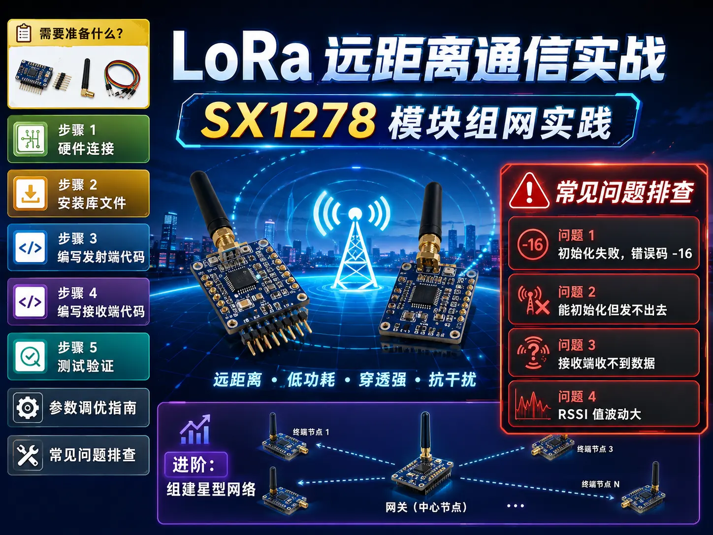
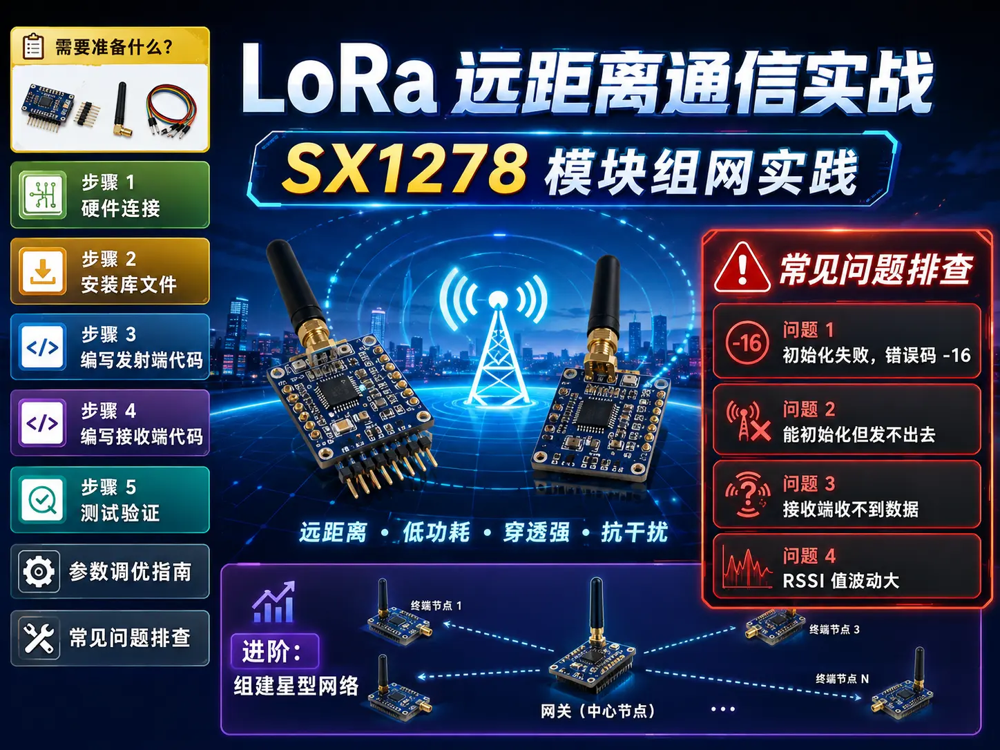
 LoRa Long-Range Communication in Practice: SX1278 Module Networking Guide
Foreword: IoT project developers have all encountered this problem: WiFi can’t reach far enough, Bluetooth is too short-range, and 4G is too expensive. Today we’ll talk about LoRa—the “magical radio” that can transmit 10km in suburbs and 3km in cities.
Last week a friend doing agricultural monitoring asked me for help. He needed to deploy soil moisture sensors in an orchard, with the farthest ones 2km from the control room. WiFi? Forget about it. 4G? Each node costs 20 yuan/month in data fees, 100 nodes would be 2000 yuan/month, too expensive. In the end, we used a LoRa solution with 8 gateways covering the entire 500-acre orchard, with monthly electricity costs under 50 yuan.
Today I’ll share this complete solution with you.
What Do You Need?
| Item | Specification | Reference Price | Quantity | Subtotal |
|---|---|---|---|---|
| LoRa Module SX1278 | 868MHz | ¥35 | 2 | ¥70 |
| Arduino Nano | ATmega328P | ¥15 | 2 | ¥30 |
| 868MHz Spring Antenna | SMA connector | ¥12 | 2 | ¥24 |
| Breadboard + Jumper Wires | 20cm | ¥5 | 10 | ¥50 |
| USB Data Cable | Mini USB | ¥5 | 2 | ¥10 |
| USB-TTL Programmer | CH340 | ¥8 | 1 | ¥8 |
| Total | ¥192 |
💡 Money-saving tip: Search for “LoRa kit” on Taobao, buy integrated SX1278+Arduino boards, two sets cost about ¥150, more cost-effective. I bought them separately this time to demonstrate wiring details.
Step 1: Hardware Connection
The SX1278 module has 8 pins, we only need to connect 7. Follow me:
SX1278      →   Arduino Nano
---------       ------------
VCC         →   3.3V   ⚠️ Don't connect to 5V, will burn the module!
GND         →   GND
NSS (CSN)   →   D10
MOSI        →   D11
MISO        →   D12
SCK         →   D13
RST         →   D9
DIO0        →   D2  (Interrupt pin, must connect!)
⚠️ Pitfall warning:
-
SX1278 is a 3.3V module, absolutely cannot connect to 5V, otherwise it will burn out immediately. The Arduino Nano’s 3.3V pin has limited output current (about 50mA), but LoRa transmission requires about 120mA instantaneously. For long-range transmission, it’s recommended to use external 3.3V regulated power supply.
-
The NSS chip select pin can be adjusted as needed, doesn’t have to be D10, but the code should match
Module(10, 2, 9, 3)first parameter. -
DIO0 must connect to an interrupt pin (D2 or D3 on Arduino Nano), otherwise the receiver’s
setDio0Action()callback won’t trigger, and you’ll never receive data.
It’s recommended to use a multimeter’s continuity test mode to check each connection after wiring. LoRa is quite sensitive to SPI signal quality, poor soldering or loose connections will cause initialization to fail.
Step 2: Install Library
We’ll use the RadioLib library, which is more actively maintained than the older RadioHead and supports more chips.
# Open Arduino IDE
# Tools → Manage Libraries → Search "RadioLib" → Install (v6.5.0 or newer)
Or manually download:
cd ~/Arduino/libraries
git clone https://github.com/jgromes/RadioLib.git
Step 3: Write Transmitter Code
Create a new sketch, name it LoRa_Transmitter:
#include <RadioLib.h>

// SX1278 pin definitions
SX1278 lora = new Module(10, 2, 9, 3);  // NSS, DIO0, RST, DIO1

int counter = 0;

void setup() {
  Serial.begin(9600);

  // Initialize LoRa
  int state = lora.begin();
  if (state == RADIOLIB_ERR_NONE) {
    Serial.println("LoRa initialization successful!");
  } else {
    Serial.print("Initialization failed, error code: ");
    Serial.println(state);
    while (true);
  }

  // Configure parameters (can be adjusted based on distance)
  state = lora.setFrequency(868.0);      // Frequency 868MHz
  state = lora.setBandwidth(125.0);      // Bandwidth 125kHz
  state = lora.setSpreadingFactor(9);    // Spreading factor 7-12 (higher = longer range, slower speed)
  state = lora.setCodingRate(5);         // Coding rate 5-8 (error tolerance)
  state = lora.setSyncWord(0x12);        // Sync word (must be same for same network)
  state = lora.setOutputPower(17);       // Transmit power 10-17dBm

  Serial.println("Configuration complete, starting to send...");
}

void loop() {
  String message = "Hello LoRa #" + String(counter) +
                   " | Temp: " + String(random(20, 35)) +
                   "°C | Humi: " + String(random(40, 80)) + "%";

  Serial.print("Sending: ");
  Serial.println(message);

  int state = lora.transmit(message);

  if (state == RADIOLIB_ERR_NONE) {
    Serial.println("✓ Send successful!");
  } else {
    Serial.print("✗ Send failed, error code: ");
    Serial.println(state);
  }

  counter++;
  delay(5000);  // Send once every 5 seconds
}
Step 4: Write Receiver Code
Flash this LoRa_Receiver on the other board:
#include <RadioLib.h>

SX1278 lora = new Module(10, 2, 9, 3);

// Interrupt flag
volatile bool receivedFlag = false;

void setFlag(void) {
  receivedFlag = true;
}

void setup() {
  Serial.begin(9600);

  int state = lora.begin();
  if (state != RADIOLIB_ERR_NONE) {
    Serial.print("Initialization failed: ");
    Serial.println(state);
    while (true);
  }

  // Configuration must match transmitter!
  lora.setFrequency(868.0);
  lora.setBandwidth(125.0);
  lora.setSpreadingFactor(9);
  lora.setCodingRate(5);
  lora.setSyncWord(0x12);

  // Set interrupt callback
  lora.setDio0Action(setFlag);

  // Start listening
  state = lora.startReceive();
  if (state == RADIOLIB_ERR_NONE) {
    Serial.println("Starting to listen...");
  } else {
    Serial.print("Listen failed: ");
    Serial.println(state);
  }
}

void loop() {
  if (receivedFlag) {
    receivedFlag = false;

    String message;
    int state = lora.readData(message);

    if (state == RADIOLIB_ERR_NONE) {
      Serial.println("✓ Data received:");
      Serial.println(message);

      // Print RSSI (signal strength)
      float rssi = lora.getRSSI();
      Serial.print("Signal strength: ");
      Serial.print(rssi);
      Serial.println(" dBm");
    } else {
      Serial.print("✗ Read failed: ");
      Serial.println(state);
    }

    // Continue listening
    lora.startReceive();
  }
}
Step 5: Test and Verify
After flashing both boards:
- Power on the transmitter first, open serial monitor (9600 baud rate), observe if it prints “Send successful” every 5 seconds.
- Then power on the receiver, observe if the serial port displays received data and corresponding RSSI signal strength.
- If both ends are working normally, try gradually increasing the distance to test actual communication range.
My test results:
Sending: Hello LoRa #0 | Temp: 28°C | Humi: 65%
✓ Send successful!
✓ Data received:
Hello LoRa #0 | Temp: 28°C | Humi: 65%
Signal strength: -42 dBm
🏃 Long-range test:
- I placed the transmitter on the rooftop, receiver indoors
- Straight-line distance about 800 meters, through 3 walls
- RSSI dropped to -95 dBm, but still receiving stably
- According to official data, SX1278 can achieve 10km+ in open areas
Parameter Tuning Guide
Different scenarios require different configurations, remember this trade-off:
| Scenario | SF | BW | CR | Power | Characteristics |
|---|---|---|---|---|---|
| Urban buildings | SF9 | 125kHz | 4/5 | 17dBm | Balanced,兼顾 distance and speed |
| Suburban open areas | SF11 | 125kHz | 4/7 | 17dBm | Distance priority, can reach 5km+ |
| Indoor short range | SF7 | 500kHz | 4/5 | 10dBm | Speed priority, low latency |
| Battery powered | SF10 | 125kHz | 4/8 | 14dBm | Low power, sacrifices speed for reliability |
My recommended configurations:
-
Urban buildings: SF9 / BW125 / CR5 / 17dBm (balanced)
-
Suburban open areas: SF11 / BW125 / CR7 / 17dBm (distance priority)
-
Indoor short range: SF7 / BW500 / CR5 / 10dBm (speed priority)
Common Problem Troubleshooting
Problem 1: Initialization failed, error code -16
Symptom: Serial port prints Initialization failed, error code: -16
Cause: SPI communication failure, usually a wiring issue
Solution:
- Check if VCC is connected to 3.3V (not 5V), measure voltage with multimeter.
- Use multimeter continuity mode to test the four SPI wires (MOSI/MISO/SCK/NSS) for connectivity, eliminate poor soldering.
- Confirm jumper wires are not loose, breadboard contacts are good; try a different hole position.
Problem 2: Can initialize but can’t transmit
Symptom: Initialization succeeds, but transmit() returns error code -702
Cause: DIO0 pin not connected or connected incorrectly
Solution:
- Check if the jumper wire from DIO0 to D2 is properly connected, unplug and reconnect.
- Confirm the second parameter of
new Module(10, 2, 9, 3)in the code (DIO0) matches the actual wiring. - Try power cycling the module, in some cases the RST pin’s capacitor can cause incomplete initialization.
Problem 3: Receiver can’t receive data
Symptom: Transmitter shows send successful, receiver has no response
Troubleshooting steps:
- Check if parameters on both ends are exactly the same: frequency, SF, BW, CR, SyncWord, any mismatch will prevent reception.
- Confirm both ends’ code has the same
SyncWord(default0x12, different networks must use different values to isolate). - Try bringing both ends close together within 1 meter to test, eliminate distance or antenna issues.
- Check if antenna is properly connected; antenna断路 or poor soldering will cause extremely weak signal, disconnect and reconnect the antenna.
Problem 4: RSSI values fluctuate greatly
Symptom: Signal strength varies at the same location
Cause: Multipath effect (radio reflection interference)
Solution:
- Use external spring antenna or rubber duck antenna instead of PCB antenna, radiation pattern is more stable.
- Avoid antenna near metal objects or human body (human body has high water content, significant attenuation to 868MHz signals).
- Take multiple samples and average, recommend taking median of 5-10 RSSI readings as final value.
Advanced: Building Star Network
The above example is point-to-point, in actual projects we commonly use star topology:
[Gateway]
/  |  \
/   |   \
[Node 1] [Node 2] [Node 3]
Implementation approach:
- Gateway side: Write receiving program, continuously listen and parse data from different
nodeId, store grouped by ID. - Node side: Each node is assigned a unique
nodeId(1-254) in code, periodically collects sensor data and reports. - Data packet structure: Add
nodeIdbyte identifier at the beginning of payload, gateway uses this to distinguish data sources (e.g.,"1,28.5,65"represents node 1, temperature 28.5℃, humidity 65%). - Optional ACK mechanism: Node waits for gateway to reply with an ACK byte within 200ms after sending, timeout then retransmit (up to 3 times), improves reliability.
Data packet structure example:
struct SensorData {
  uint8_t nodeId;      // Node ID (1-254)
  float temperature;   // Temperature
  float humidity;      // Humidity
  uint16_t battery;    // Battery voltage (mV)
  uint8_t crc;         // Checksum
};
I used this architecture in the orchard project, 8 gateways with 120 nodes, ran stably for a year.
Summary
LoRa isn’t a panacea, but it’s really good in specific scenarios:
✅ Suitable for LoRa:
-
Transmission distance 1-10km
-
Small data volume (tens of bytes each time)
-
Low frequency transmission (once every few minutes)
-
Battery powered (standby current <1μA)
❌ Don’t use LoRa:
-
Need to transmit images/audio
-
Require high bandwidth (>10kbps)
-
Dense urban areas (severe interference)
-
High-speed mobile scenarios
Today’s SX1278 solution costs only 192 yuan, much cheaper than buying commercial development boards. Modify it a bit, make a smart parking sensor, warehouse temperature/humidity monitoring, or even a mountain bike tracker, all work great.
Next steps you can try:
- Add a GPS module for asset tracking
- Use solar panels for permanent power
- Integrate with Home Assistant for smart home
Leave questions in the comments, I’ll reply when I see them.
Related resources:
Hardware Purchase Links:
- SX1278 module: Search “Ra-02 868MHz” on Taobao
- Arduino Nano: Search “Arduino Nano CH340” on Taobao