 Embedded Development
 Relay Module Safe Usage: High-Power Device Control
Why You Need to Understand Relay Safe Usage
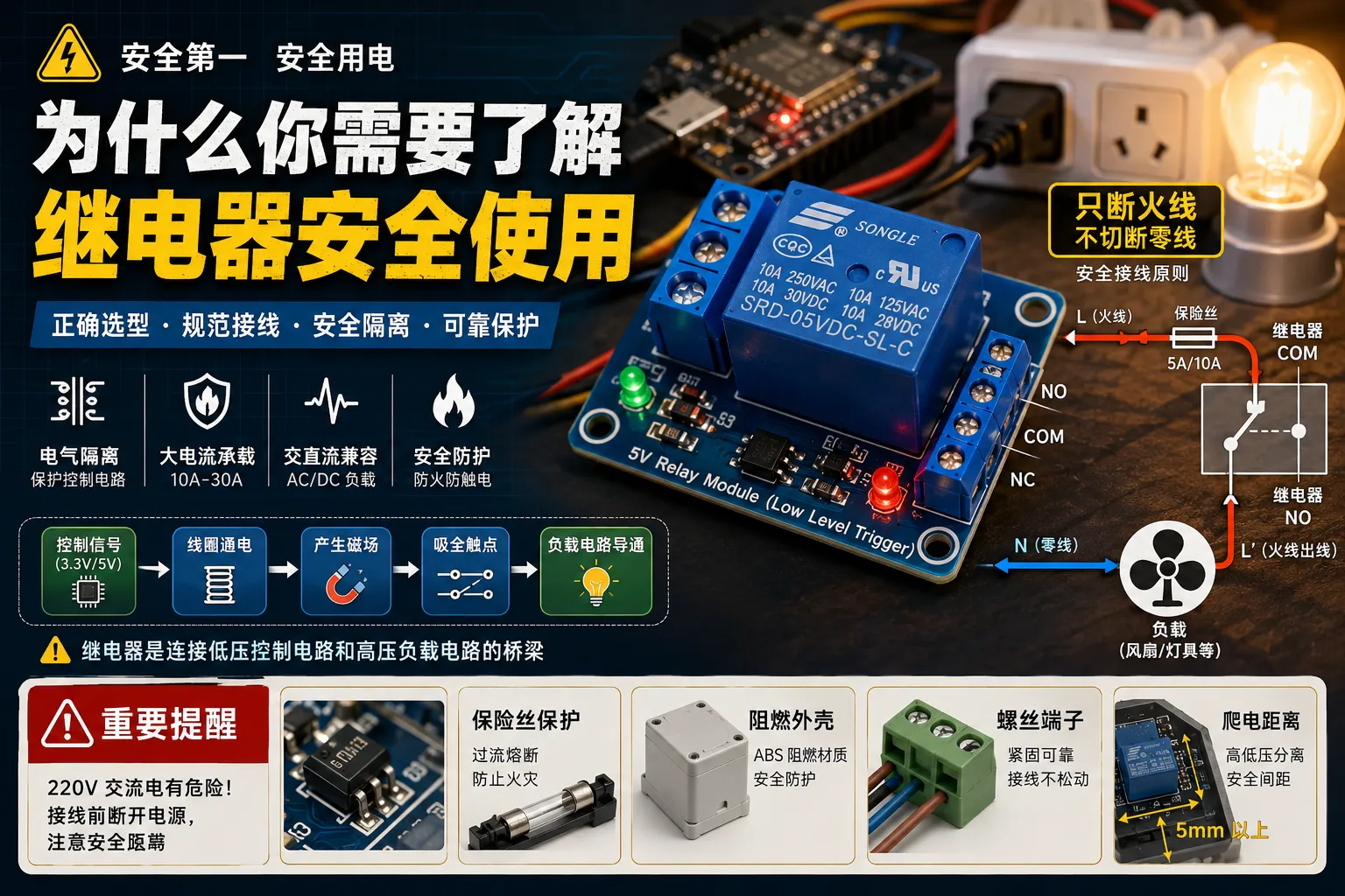
Controlling an LED is simple, but when you want to control 220V AC-powered devices - like lights, fans, water pumps, heaters - things aren’t that simple anymore. Relays are the bridge between low-voltage control circuits and high-voltage load circuits, but if used improperly, at best they’ll burn out the module, at worst they can cause fire or electric shock accidents.
In this article I’ll take you from zero to understanding relay module selection, wiring, safety isolation design, and those details that are easily overlooked but critically important.
Relay Working Principle Quick Overview
A relay is essentially an electromagnetic switch:
Control signal (3.3V/5V) → Coil energized → Generates magnetic field → Contacts close → Load circuit conductsKey characteristics:
-
Electrical isolation: Control side and load side are completely isolated, safe
-
High current capacity: Common relays can handle 10A-30A current
-
AC/DC compatible: Contacts can switch AC or DC loads
Hardware List
| Component | Model/Specification | Reference Price | Notes |
|---|---|---|---|
| Relay module | 5V 1-channel/2-channel/4-channel | ¥15-35 | Recommend optocoupler isolated type |
| Relay | SRD-05VDC-SL-C | ¥3-8 | 10A 250VAC |
| Development board | Arduino/ESP32/STM32 | ¥20-50 | Any GPIO controllable |
| Jumper wires | Male-to-female/Female-to-female | ¥5 | For wiring |
| Terminal blocks | 2P/3P screw terminals | ¥2 | For fixing AC wires |
| Fuse | 5A/10A slow-blow | ¥3 | Overcurrent protection |
| Flame-retardant enclosure | ABS plastic box | ¥10-20 | Safety protection |
Recommended purchase keywords: 5V relay module optocoupler isolated, SRD-05VDC-SL-C
Relay Module Type Selection
1. Low-Level Trigger vs High-Level Trigger
This is the easiest place to make mistakes!
Low-level trigger (common):
-
GPIO outputs LOW (0V) → Relay engages
-
GPIO outputs HIGH (3.3V/5V) → Relay disengages
-
Most commercially available modules use this design
High-level trigger:
-
GPIO outputs HIGH → Relay engages
-
GPIO outputs LOW → Relay disengages
-
Logic is more intuitive, but less common
How to determine: Check module silkscreen or test: GPIO floating state = default state
2. Importance of Optocoupler Isolation
Be sure to choose modules with optocoupler isolation!
Without optocoupler: GPIO → Transistor → Relay coil (risky)
With optocoupler: GPIO → Optocoupler → Transistor → Relay coil (safe isolation)
Benefits of optocoupler isolation:
-
Prevents high-voltage side surges from reverse-breaking MCU
-
Reduces electromagnetic interference impact on control circuit
-
Improves system reliability
Wiring Details (Using 5V Low-Level Trigger Module as Example)
Control Side Wiring
ESP32/Arduino     Relay Module
────────────      ────────────
5V         →      VCC
GND        →      GND
GPIO 4 → IN1Notes:
-
ESP32 GPIO outputs 3.3V, but most 5V relay modules can recognize it
-
If relay doesn’t engage, check if module supports 3.3V logic
-
For high-current loads, shared ground between control side and load side may introduce interference, recommend isolated power supply
Load Side Wiring (220V AC)
Relay modules typically have 3 terminal blocks:
┌─────────────────┐
│    Relay        │
│                 │
│  COM   Common   │────→ Live wire input (L)
│  NC    Normally Closed │────→ Not used (usually left empty)
│  NO    Normally Open   │────→ Live wire output (L') → Load
└─────────────────┘

Neutral (N) connects directly to load, doesn't go through relay
Complete wiring diagram:
220V AC Power
    │
    ├── L (Live) ────→ Relay COM
    │                    Relay NO ────→ Load L terminal
    │
    └── N (Neutral) ────────────────────→ Load N terminal
Key principle: Relay only breaks the live wire, not the neutral wire!
Code Examples (ESP32/Arduino)
Basic Control
// Relay control pin
#define RELAY_PIN 4

void setup() {
  pinMode(RELAY_PIN, OUTPUT);
  digitalWrite(RELAY_PIN, HIGH);  // Low-level trigger module: HIGH = disengaged
  Serial.begin(115200);
}

void loop() {
  // Turn on relay (engage)
  digitalWrite(RELAY_PIN, LOW);
  Serial.println("Relay engaged - Device on");
  delay(5000);

  // Turn off relay (disengage)
  digitalWrite(RELAY_PIN, HIGH);
  Serial.println("Relay disengaged - Device off");
  delay(5000);
}
Encapsulation with State Feedback
class RelayController {
private:
  int pin;
  bool triggerLow;  // Whether low-level trigger
  bool currentState;

public:
  RelayController(int _pin, bool _triggerLow = true)
    : pin(_pin), triggerLow(_triggerLow), currentState(false) {
    pinMode(pin, OUTPUT);
    digitalWrite(pin, triggerLow ? HIGH : LOW);  // Initially disengaged
  }

  void on() {
    digitalWrite(pin, triggerLow ? LOW : HIGH);
    currentState = true;
  }

  void off() {
    digitalWrite(pin, triggerLow ? HIGH : LOW);
    currentState = false;
  }

  void toggle() {
    currentState ? off() : on();
  }

  bool isOn() {
    return currentState;
  }
};

// Usage example
RelayController relay(4, true);  // GPIO 4, low-level trigger

void loop() {
  relay.on();
  delay(10000);
  relay.off();
  delay(10000);
}
Safety Design Key Points (Must Read!)
1. Fuse Protection
Connect fuse in series on live wire input side:
Mains → Fuse → Relay COM → NO → Load
         ↑
       5A/10A slow-blow fuse
Function: Melts when load shorts or overcurrents, preventing fire
2. Flame-Retardant Enclosure
Never expose bare 220V wiring in the air!
-
Use ABS flame-retardant plastic box
-
Use rubber cable grommets for entry/exit holes
-
Leave sufficient space inside box, avoid wire compression
3. Terminal Block Tightening
-
Use screw terminals, don’t just twist wires together
-
Gently pull wires after tightening to confirm they don’t loosen
-
Tin stranded wires first or use cold-press terminals
4. Creepage Distance
Keep distance between high-voltage side and low-voltage side wiring:
-
Minimum spacing 5mm or more
-
Avoid parallel wiring being too long
-
Slot isolation when necessary
5. Avoid Direct Switching of Inductive Loads
When relays switch inductive loads like motors, transformers, arcs will be generated:
Solutions:
-
Parallel RC snubber circuit (100Ω + 0.1μF)
-
Or use solid state relay (SSR)
-
Or choose relay capacity with 2x margin
Common Problem Troubleshooting
Problem 1: Relay Doesn’t Engage
Possible causes:
-
GPIO level mismatch (3.3V vs 5V)
-
Insufficient supply current (USB power can’t drive multiple relays)
-
Trigger logic reversed (low-level vs high-level)
Troubleshooting steps:
-
Use multimeter to measure GPIO pin output voltage, confirm if level reaches module trigger threshold (low-level trigger needs <0.8V, high-level trigger needs >2.5V)
-
Check if module power supply is normal, use independent 5V/1A power supply instead of USB power to test, rule out insufficient current issue
-
Confirm trigger logic - disconnect signal wire, observe relay default state: if default engaged then it’s low-level trigger, if default disengaged then it’s high-level trigger
Problem 2: Relay Engages Then Immediately Disengages
Possible causes:
-
Insufficient power capacity, voltage drops during engagement instant
-
Code logic issue (rapid toggle)
-
Watchdog reset
Solution:
-
Use independent 5V/2A power supply for relay
-
Shared ground between control side and load side
Problem 3: ESP32 Restarts or Freezes
Possible causes:
-
Electromagnetic interference generated during relay switching instant
-
No optocoupler isolation, surge reverse-breaks
Solution:
-
Replace with relay module with optocoupler
-
Separate relay power supply from MCU power supply
-
Parallel flyback diode across relay coil terminals
Problem 4: Load Device Works Abnormally
Possible causes:
-
Relay contact resistance is large
-
Live/neutral wires reversed
-
Load power exceeds relay rated value
Solution:
-
Check if wiring is correct (only breaks live wire)
-
Confirm load current < 80% of relay rated current
-
Replace with larger capacity relay
Advanced: Multi-Channel Relay Control
For scenarios requiring control of multiple devices:
#define RELAY_COUNT 4
int relayPins[] = {4, 5, 6, 7};
bool relayState[] = {false};

void setup() {
  for (int i = 0; i < RELAY_COUNT; i++) {
    pinMode(relayPins[i], OUTPUT);
    digitalWrite(relayPins[i], HIGH);  // All initially off
  }
}

void setRelay(int index, bool state) {
  if (index >= RELAY_COUNT) return;
  digitalWrite(relayPins[index], state ? LOW : HIGH);
  relayState[index] = state;
}

// Turn all off (safe default state)
void allOff() {
  for (int i = 0; i < RELAY_COUNT; i++) {
    setRelay(i, false);
  }
}
Application scenarios:
-
Smart home multi-channel lighting control
-
Fish tank timed feeding + lighting + filtration system
-
Greenhouse multi-device management
Relay Lifespan and Maintenance
Mechanical relays have lifespan limits:
-
Electrical lifespan: About 100,000 times (rated load)
-
Mechanical lifespan: About 10 million times (no load)
Tips to extend lifespan:
-
Avoid frequent switching (minimum interval 1-2 seconds)
-
Don’t use overloaded
-
Regularly check if contacts are oxidized and blackened
-
Consider switching to solid state relay for high-current loads
Summary
Relays are key components for controlling high-power devices in IoT projects, but safety always comes first:
-
Must connect fuse in series on live wire input side, can cut power supply immediately when load shorts
-
Relay only breaks live wire, neutral wire connects directly to load - this is basic electrical safety standard
-
Choose relay modules with optocoupler isolation to prevent high-voltage side surges from damaging MCU
-
All 220V wiring must be installed in flame-retardant enclosure, terminal blocks tightened with screws, absolutely no exposed live parts allowed
Remember: 220V AC is not a toy. Disconnect power before each wiring, maintain safe distance observation during first power-on.
Hope this blog post is helpful to you!