 Electronics
 2026 RJ45 and POE Pinout Guide
In today’s connected world, we’re all linked together. The pinout definitions for the most basic RJ45 interface (commonly called crystal head) may be essential reference material for engineering or troubleshooting. However, the POE protocol built on RJ45 is also frequently used in video surveillance, device power supply, and other applications. This article briefly summarizes the different pin definitions in RJ45 interfaces and POE specifications to help engineers with quick reference.
RJ45 Interface
Crystal head (English: Registered Jack, RJ), RJ45 is a standardized telecommunications network interface. The connector consists of a plug (connector, crystal head) and a socket (module). The plug has 8 slots and 8 contacts. In FCC (Federal Communications Commission) standards and regulations, RJ describes public telecommunications network interfaces. The computer network’s RJ45 is the common name for a standard 8-position modular interface.
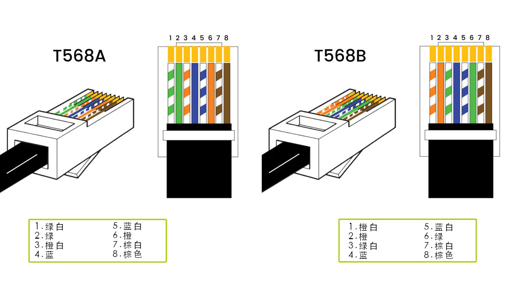
T568A vs T568B Color Codes
T568A and T568B are two color codes for terminating eight-position RJ45 modular plugs. Both are permitted under the ANSI/TIA-568-C wiring standard. The only difference between T568A and T568B is that the orange and green pairs are swapped.
Pin Definitions
There are two types of common RJ45 interfaces: DTE (Data Terminal Equipment) type used for Ethernet network cards, router Ethernet ports, etc., and DCE (Data Circuit-terminating Equipment) type used for switches, etc. When connecting two devices of the same type using RJ45 interfaces for communication, a crossover cable must be used. If DTE type interfaces are connected to DTE type interfaces without crossing the pins, the connected pins are all data receive (transmit) pins, and communication cannot occur. Additionally: some DCE type devices will auto-negotiate with the other party, in which case either a straight-through or parallel cable can be used.
| Ethernet 10/100Base-T Interface | Ethernet 100Base-T4 Interface |
|---|---|
| Pin No. | Pin Name |
| 1 | TX+ |
| 2 | TX- |
| 3 | RX+ |
| 4 | n/c |
| 5 | n/c |
| 6 | RX- |
| 7 | n/c |
| 8 | n/c |
About POE
Power over Ethernet (PoE), also called PoE power supply, is a set of standardized or proprietary technologies that can transmit both power and data over Ethernet twisted pair cables. It can provide power and data transmission to wireless access points (WAPs), network cameras, and VoIP phones through just one Ethernet twisted pair cable.
Currently, there are multiple technical standards for transmitting power and data simultaneously over twisted pair cables. Three of them were standardized into IEEE 802.3 by the Institute of Electrical and Electronics Engineers (IEEE) in 2003, called Mode A, Mode B, and 4PPoE respectively. For 10BASE-T and 100BASE-TX, these technologies only use two of the four pairs in CAT5 twisted pair cables.
Active PoE vs Passive PoE
-
Active PoE is the abbreviation for active Power over Ethernet, also called standard PoE. It refers to any type of PoE that negotiates the appropriate voltage between the power sourcing equipment (PSE) and PD devices. Active PoE switches are devices that comply with standard PoE, so they’re also called standard PoE switches. This type of switch is rated for compliance with IEEE 802.3af, IEEE 802.3at, or IEEE 802.3bt standards. Therefore, it can be further divided into PoE, PoE+, and PoE++ switches. Before powering on, an active PoE switch will test and check to ensure power compatibility between the switch and remote device. Otherwise, the active PoE switch will not supply power, preventing potential damage to non-PoE devices.
-
Passive PoE, also called passive Ethernet power supply, is a non-standard PoE. It can also supply power over Ethernet lines, but without negotiation or communication processes. Passive PoE switches do not comply with any IEEE standards. When using passive PoE switches in a network, the power is “always on,” meaning it always sends current over the Ethernet cable at a certain voltage regardless of whether the terminal device supports PoE. Therefore, if the terminal device is not prepared for a live Ethernet cable, using a passive PoE switch may burn out the terminal device.
Mode A and Mode B for RJ45 Twisted Pair
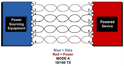
10/100 and Gigabit Ethernet cables have four pairs of twisted pairs, corresponding to 8 pins. The 802.3af standard specifies that for 10/100 Ethernet cables, only two of the four pairs can transmit data, while the other two pairs can be used for power supply. Among these pairs, 10/100 Ethernet only allows data transmission over two pairs (four wires). Power is supplied through either Mode A or Mode B.
-
Mode A leaves two twisted pairs unused and transmits both data and power over the outer pairs 1,2 and 3,6. This method is best when both power and data come from the same PSE, so it’s also called Endspan.
-
Mode B works by having two dedicated pairs (pins 4,5+ and 7,8-) exclusively for power transmission, while the other two pairs are for data. Since PoE adapters (injectors) take standard data Ethernet and “inject” power into the cable, they more often use Mode B to power devices. Therefore, Mode B is sometimes called Midspan.
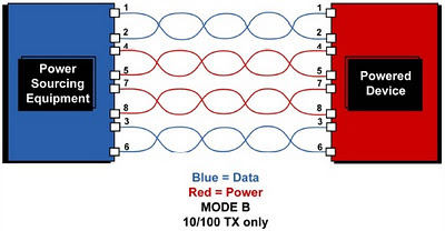
| 10/100M Twisted Pair Network | 1000M Twisted Pair Network | |
|---|---|---|
| Switch Pin | PoE Mode A (Data and DC power mixed) | PoE Mode B (DC power separated) |
| Pin 1 | Rx+ and DC+ | Rx+ |
| Pin 2 | Rx- and DC+ | Rx- |
| Pin 3 | Tx+ and DC- | Tx+ |
| Pin 4 | Unused | DC+ |
| Pin 5 | Unused | DC+ |
| Pin 6 | Tx- and DC- | Tx- |
| Pin 7 | Unused | DC- |
| Pin 8 | Unused | DC- |