
 Electronics
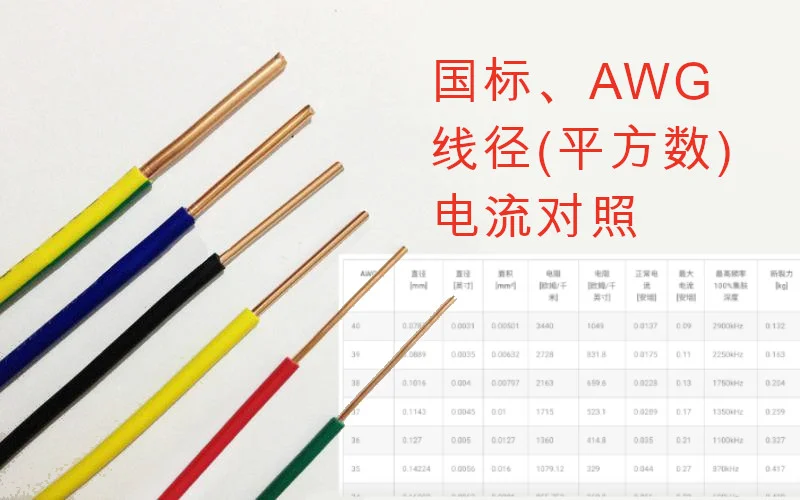
 Wire Gauge Current Rating Table: AWG SWG Quick Reference (2026 Practical Guide)
About Standards
There are three commonly used international standards for wire specifications: American (AWG), British (SWG), and Chinese (CWG).
The “square millimeter” rating is a nominal value specified by national standards. Users choose wire gauge based on the load requirements of their electrical cables.
Wire gauge (in square millimeters) is a common term used in electrical installation work. When people say “X square wire,” they’re referring to square millimeters without explicitly stating the unit.
The “square” of a wire actually refers to the cross-sectional area of the wire — the area of the circular cross-section, measured in square millimeters.
Generally speaking, the empirical current capacity is that when the grid voltage is 220V, each square millimeter of wire can carry about 1 kilowatt.
Copper wire can carry 1-1.5 kilowatts per square millimeter, while aluminum wire can carry 0.6-1 kilowatts per square millimeter. Therefore, a 1-kilowatt appliance only needs 1 square millimeter of copper wire.
Specifically for current, during short-distance power transmission, copper wire can generally carry 3A to 5A per square millimeter. Use 5A/sq mm when cooling conditions are good, and 3A/sq mm when they’re not.
Chinese National Standard
According to the national standard “GB/T 4706.1-2005,” we can find the following definitions for qualified conductors:
| Appliance Rated Current A | Flexible Cable Cross-section (mm²) | Fixed Wiring Cable Cross-section (mm²) |
|---|---|---|
| ≤3 | 0.5 and 0.75 | 1-2.5 |
| >3 and ≤6 | 0.75 and 1 | 1-2.5 |
| >6 and ≤10 | 1 and 1.5 | 1-2.5 |
| >10 and ≤16 | 1.5 and 2.5 | 1.5-4 |
| >16 and ≤25 | 2.5 and 4 | 2.5-6 |
| >25 and ≤32 | 4 and 6 | 4-10 |
| >32 and ≤40 | 6 and 10 | 6-16 |
| >40 and ≤63 | 10 and 16 | 10-25 |
Stranded Wire Cross-section Calculation
Knowing the wire gauge (in square millimeters), calculate the wire radius using the circle area formula:
Wire gauge (mm²) = π (3.14) × wire radius (mm)²
Knowing the wire gauge, calculating wire diameter works the same way. For example:
The wire diameter of 2.5 sq mm wire is: 2.5 ÷ 3.14 = 0.8, then take the square root to get 0.9 mm. Therefore, the wire diameter of 2.5 sq mm wire is: 2 × 0.9 mm = 1.8 mm.
Knowing the wire diameter, calculating wire gauge also uses the circle area formula:
Wire gauge = π (3.14) × wire diameter² / 4
Cable sizes are also labeled in square millimeters. For stranded wire, it’s the sum of the cross-sectional areas of each conductor.
Cable cross-section calculation formula:
0.7854 × wire radius (mm)² × number of strands
For example, 48 strands (each strand radius 0.2 mm) 1.5 sq mm wire:
0.785 × (0.2 × 0.2) × 48 = 1.5 sq mm
American Wire Gauge AWG
The American Wire Gauge (AWG) size and characteristics chart lists the AWG dimensions of cables/conductors. In addition to wire size, the table provides values for load (current) carrying capacity, resistance, and skin effect.
Current Carrying Capacity
Definition: Current carrying capacity is the wire’s ability to carry current. In other words, how many amperes can it transmit? The table below is a guide for load current or copper wire current carrying capacity, following the American Wire Gauge spreadsheet and formula handbook. As you might guess, the rated current capacity is just a rule of thumb. In careful engineering design, voltage drop, insulation temperature limits, thickness, thermal conductivity, air convection, and temperature should all be considered. The maximum amperage for power transmission uses the rule of 700 circular mils per amp, which is very, very conservative. The maximum amperage for chassis wiring is also a conservative rating, but it applies to wiring in air, not bundled. For shorter wires, such as those used for battery packs, you should weigh resistance and load against size, weight, and flexibility.
100% Skin Depth Maximum Frequency
This data is useful for high-frequency AC engineering. When conducting high-frequency AC through a wire, current tends to flow along the outer surface of the wire. This increases effective resistance. The frequencies listed in the table show the calculated skin depth equal to the wire radius, indicating that above this frequency, you should start considering skin effect when calculating wire resistance.
Reference Table (Copper Wire)
@media only screen and (max-width: 600px) { table td,table th { padding: 0px; } .mobile { display:block; } table{ display:none; } } @media only screen and (min-width: 601px) { .mobile { display:none; } table{ display:block; } }
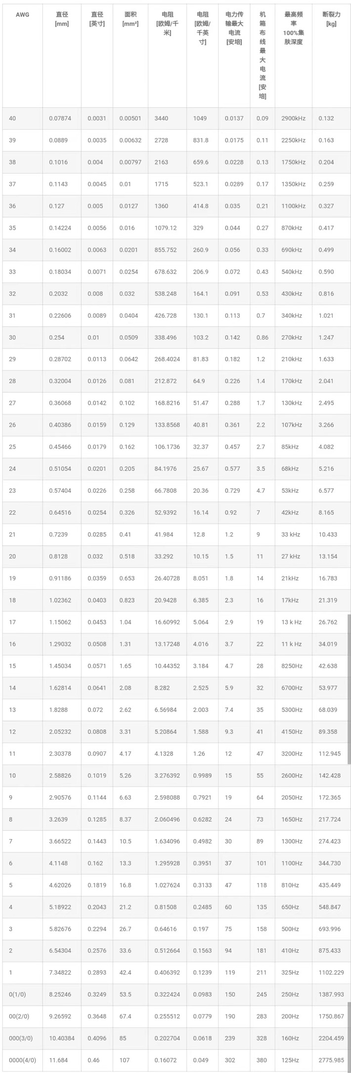
| AWG | Diameter | Diameter [inches] | Area | Resistance [Ω/km] | Resistance [Ω/kilo-inch] | Power Transfer Max Current [Amps] | Chassis Wiring Max Current [Amps] | Max Frequency 100% Skin Depth | Breaking Force |
|---|---|---|---|---|---|---|---|---|---|
| 40 | 0.07874 | 0.0031 | 0.00501 | 3440 | 1049 | 0.0137 | 0.09 | 2900kHz | 0.132 |
| 39 | 0.0889 | 0.0035 | 0.00632 | 2728 | 831.8 | 0.0175 | 0.11 | 2250kHz | 0.163 |
| 38 | 0.1016 | 0.004 | 0.00797 | 2163 | 659.6 | 0.0228 | 0.13 | 1750kHz | 0.204 |
| 37 | 0.1143 | 0.0045 | 0.01 | 1715 | 523.1 | 0.0289 | 0.17 | 1350kHz | 0.259 |
| 36 | 0.127 | 0.005 | 0.0127 | 1360 | 414.8 | 0.035 | 0.21 | 1100kHz | 0.327 |
| 35 | 0.14224 | 0.0056 | 0.016 | 1079.12 | 329 | 0.044 | 0.27 | 870kHz | 0.417 |
| 34 | 0.16002 | 0.0063 | 0.0201 | 855.752 | 260.9 | 0.056 | 0.33 | 690kHz | 0.499 |
| 33 | 0.18034 | 0.0071 | 0.0254 | 678.632 | 206.9 | 0.072 | 0.43 | 540kHz | 0.590 |
| 32 | 0.2032 | 0.008 | 0.032 | 538.248 | 164.1 | 0.091 | 0.53 | 430kHz | 0.816 |
| 31 | 0.22606 | 0.0089 | 0.0404 | 426.728 | 130.1 | 0.113 | 0.7 | 340kHz | 1.021 |
| 30 | 0.254 | 0.01 | 0.0509 | 338.496 | 103.2 | 0.142 | 0.86 | 270kHz | 1.247 |
| 29 | 0.28702 | 0.0113 | 0.0642 | 268.4024 | 81.83 | 0.182 | 1.2 | 210kHz | 1.633 |
| 28 | 0.32004 | 0.0126 | 0.081 | 212.872 | 64.9 | 0.226 | 1.4 | 170kHz | 2.041 |
| 27 | 0.36068 | 0.0142 | 0.102 | 168.8216 | 51.47 | 0.288 | 1.7 | 130kHz | 2.495 |
| 26 | 0.40386 | 0.0159 | 0.129 | 133.8568 | 40.81 | 0.361 | 2.2 | 107kHz | 3.266 |
| 25 | 0.45466 | 0.0179 | 0.162 | 106.1736 | 32.37 | 0.457 | 2.7 | 85kHz | 4.082 |
| 24 | 0.51054 | 0.0201 | 0.205 | 84.1976 | 25.67 | 0.577 | 3.5 | 68kHz | 5.216 |
| 23 | 0.57404 | 0.0226 | 0.258 | 66.7808 | 20.36 | 0.729 | 4.7 | 53kHz | 6.577 |
| 22 | 0.64516 | 0.0254 | 0.326 | 52.9392 | 16.14 | 0.92 | 7 | 42kHz | 8.165 |
| 21 | 0.7239 | 0.0285 | 0.41 | 41.984 | 12.8 | 1.2 | 9 | 33 kHz | 10.433 |
| 20 | 0.8128 | 0.032 | 0.518 | 33.292 | 10.15 | 1.5 | 11 | 27 kHz | 13.154 |
| 19 | 0.91186 | 0.0359 | 0.653 | 26.40728 | 8.051 | 1.8 | 14 | 21kHz | 16.783 |
| 18 | 1.02362 | 0.0403 | 0.823 | 20.9428 | 6.385 | 2.3 | 16 | 17kHz | 21.319 |
| 17 | 1.15062 | 0.0453 | 1.04 | 16.60992 | 5.064 | 2.9 | 19 | 13 k Hz | 26.762 |
| 16 | 1.29032 | 0.0508 | 1.31 | 13.17248 | 4.016 | 3.7 | 22 | 11 k Hz | 34.019 |
| 15 | 1.45034 | 0.0571 | 1.65 | 10.44352 | 3.184 | 4.7 | 28 | 8250Hz | 42.638 |
| 14 | 1.62814 | 0.0641 | 2.08 | 8.282 | 2.525 | 5.9 | 32 | 6700Hz | 53.977 |
| 13 | 1.8288 | 0.072 | 2.62 | 6.56984 | 2.003 | 7.4 | 35 | 5300Hz | 68.039 |
| 12 | 2.05232 | 0.0808 | 3.31 | 5.20864 | 1.588 | 9.3 | 41 | 4150Hz | 89.358 |
| 11 | 2.30378 | 0.0907 | 4.17 | 4.1328 | 1.26 | 12 | 47 | 3200Hz | 112.945 |
| 10 | 2.58826 | 0.1019 | 5.26 | 3.276392 | 0.9989 | 15 | 55 | 2600Hz | 142.428 |
| 9 | 2.90576 | 0.1144 | 6.63 | 2.598088 | 0.7921 | 19 | 64 | 2050Hz | 172.365 |
| 8 | 3.2639 | 0.1285 | 8.37 | 2.060496 | 0.6282 | 24 | 73 | 1650Hz | 217.724 |
| 7 | 3.66522 | 0.1443 | 10.5 | 1.634096 | 0.4982 | 30 | 89 | 1300Hz | 274.423 |
| 6 | 4.1148 | 0.162 | 13.3 | 1.295928 | 0.3951 | 37 | 101 | 1100Hz | 344.730 |
| 5 | 4.62026 | 0.1819 | 16.8 | 1.027624 | 0.3133 | 47 | 118 | 810Hz | 435.449 |
| 4 | 5.18922 | 0.2043 | 21.2 | 0.81508 | 0.2485 | 60 | 135 | 650Hz | 548.847 |
| 3 | 5.82676 | 0.2294 | 26.7 | 0.64616 | 0.197 | 75 | 158 | 500Hz | 693.996 |
| 2 | 6.54304 | 0.2576 | 33.6 | 0.512664 | 0.1563 | 94 | 181 | 410Hz | 875.433 |
| 1 | 7.34822 | 0.2893 | 42.4 | 0.406392 | 0.1239 | 119 | 211 | 325Hz | 1102.229 |
| 0(1/0) | 8.25246 | 0.3249 | 53.5 | 0.322424 | 0.0983 | 150 | 245 | 250Hz | 1387.993 |
| 00(2/0) | 9.26592 | 0.3648 | 67.4 | 0.255512 | 0.0779 | 190 | 283 | 200Hz | 1750.867 |
| 000(3/0) | 10.40384 | 0.4096 | 85 | 0.202704 | 0.0618 | 239 | 328 | 160Hz | 2204.459 |
| 0000(4/0) | 11.684 | 0.46 | 107 | 0.16072 | 0.049 | 302 | 380 | 125Hz | 2775.985 |
References:
-
NEC (National Electrical Code) Table 310-16 Wire Ampacity Standard
-
IEC 60287 Cable Ampacity Calculation Standard