 Jetson Nano
 Jetson Nano 40-Pin Header Explained
The Jetson Nano is a compact single-board computer developed by NVIDIA, offering powerful performance at an affordable price with low power consumption — making it a favorite among makers and hobbyists.
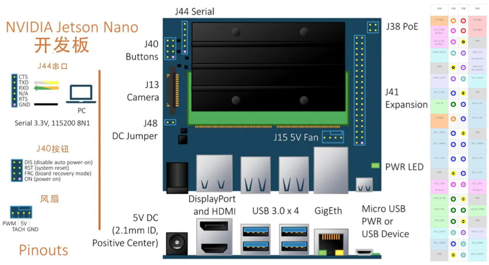
The Jetson Nano module uses a Small Outline Dual In-line Memory Module (SO-DIMM) form factor and plugs into a 100x80mm carrier board. The carrier board exposes many typical computer interfaces such as USB 3.0, Gigabit Ethernet, and video output (supporting 4K 60fps). It also features a 40-pin expansion header very similar to the one found on the Raspberry Pi. Its layout is nearly identical to the Pi’s header and even supports the Pi camera module. This article takes a detailed look at the Jetson Nano’s 40-pin header and analyzes its features and functions.
J41 Pin List
.pow33v { border: 8px solid #fd952a!important; } .pow5v { border: 8px solid #fc363b!important; } .i2c { border: 8px solid #fc4cfc!important; } .i2s { border: 8px solid #63c9cb!important; } .uart { border: 8px solid #ab60fb!important; } .spi { border: 8px solid #343ffb!important; } .gnd { background-color: black!important; line-height: 19px; border: 8px solid yellow!important; color: #ffffff; } .pin { background-color: white; width: 35px; height: 35px; line-height: 17px; position: relative; border: 8px solid green; border-radius: 100%; text-align: center; margin: 0px auto; } .pow33v-bg { background-color: #fecb9c !important; } .gnd-bg { background-color: #dddddd !important; } .pow5v-bg { background-color: #fecccd !important; } .i2c-bg { background-color: #fecdfe !important; } .i2s-bg { background-color: #d0e7f4 !important; } .spi-bg { background-color: #d0e7f4 !important; } .uart-bg { background-color: #e6e7fe !important; } .i2s-bg { background-color: #d0f7fa !important; } .gpio-bg { background-color: #cefcce !important; } table#pinout { width:100%; text-align: center; } table img { height:250px; }
| GPIO (BCM) | Name | Pin | Pin | Name | GPIO (BCM) |
|---|---|---|---|---|---|
| 3.3V Output | 1 | 2 | 5.0V Output | ||
| I2C_2_SDA**I2C Bus 1 | 3** | 4 | 5.0V Output | ||
| I2C_2_SCL**I2C Bus 1 | 5** | 6 | GND | ||
| GPIO216**(D4) | AUDIO_MCLK | 7** | 8 | UART_TX2 | |
| **/dev/ttyTHS1 | |||||
| GND | 9** | 10 | UART_RX2**/dev/ttyTHS1 | ||
| GPIO50 | |||||
| (D17) | UART_2_RTS | 11** | 12 | I2S_4_SCLK | GPIO79 |
| **(D18) | |||||
| GPIO232 | |||||
| (D23) | SPI_2_SCK | 13** | 14 | GND | |
| GPIO194**(D22) | LCD_TE | 15** | 16 | SPI_2_CS1 | GPIO232 |
| **(D23) | |||||
| 3.3V Output | 17** | 18 | SPI_2_CS0 | GPIO15 | |
| **(D24) | |||||
| GPIO16 | |||||
| (D10) | SPI_1_MOSI | 19** | 20 | GND | |
| GPIO17**(D9) | SPI_1_MOSO | 21** | 22 | SPI_2_MISO | GPIO13 |
| **(D23) | |||||
| GPIO18 | |||||
| (D11) | SPI_1_SCK | 23** | 24 | SPI_1_CS0 | GPIO19 |
| **(D8) | |||||
| GND | 25** | 26 | SPI_1_CS1 | GPIO20**(D7) | |
| I2C_1_SDA |
I2C Bus 0 | 27** | 28 | I2C_1_SCL I2C Bus 0 | | | GPIO149 (D5) | CAM_AF_EN | 29 | 30 | GND | | | GPIO200**(D6) | GPIO_PZ0 | 31** | 32 | LCD_BL_PWM | GPIO168**(D12) | | GPIO38 (D13) | GPIO_PE6 | 33** | 34 | GND | | | GPIO76**(D19) | I2S_4_LRCK | 35** | 36 | UART_2_CTS | GPIO51**(D16) | | GPIO12 (D26) | SPI_2_MOSI | 37** | 38 | I2S_4_SDIN | GPIO77**(D20) | | | GND | 39** | 40 | I2S_4_SDOUT | GPIO78 (D21) |
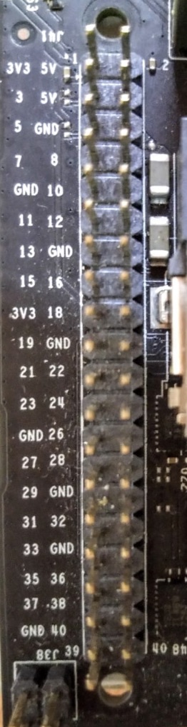
Top and Bottom Photos of the Header
| Viewed from the top of the board | Viewed from the bottom of the board |
|---|---|
 | 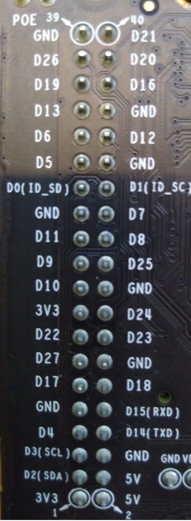 |
GPIO Pins
For those who have used a Raspberry Pi, GPIO (General Purpose Input/Output) pins are an interface through which you can connect sensors, LEDs, and other components that can be controlled programmatically (C++, Python, etc.). The Jetson Nano’s 40-pin header (J41) is physically compatible with the Raspberry Pi’s header, but the GPIO numbering differs from the Pi’s, so you’ll need to adjust your pin mappings for HAT compatibility. Like the Raspberry Pi, the Jetson Nano’s GPIO voltage is 3.3V — do not connect voltage levels above 3.3V to the Nano’s GPIO pins without using a logic level shifter.
I2C Pins
The Jetson Nano I2C controller supports system expansion through devices defined in the NXP I2C Inter-Integrated Circuit (I2C) specification. The I2C bus supports serial communication with multiple devices. The I2C controller handles clock source negotiation, speed negotiation for Standard-mode and Fast-mode devices, supports 7-bit slave addressing per the I2C protocol, and supports both master and slave operation modes.
The I2C controller supports the following operating modes: Master – Standard-mode (up to 100Kbit/s), Fast-mode (up to 400Kbit/s), Fast-mode plus (Fm+, up to 1Mbit/s); Slave – Standard-mode (up to 100Kbit/s), Fast-mode (up to 400Kbit/s), Fast-mode plus (Fm+, up to 1Mbit/s).
Power Pins
Both 5V power pins can supply up to 3A. If you’re using a carrier board with its own power supply, it can easily provide sufficient power. As for the J48 jumper header, it works with or without the jumper cap installed (GND must be connected).
References:
-
Physical Pin Number: Pins are numbered sequentially according to their physical position on the header, starting from 1. This is the most intuitive and easiest to locate.
-
BCM Numbering (Broadcom SOC Channel): Uses the internal channel numbering of the chip, which is independent of the physical position. This numbering is used when programming to specify GPIOs.