 Embedded Development
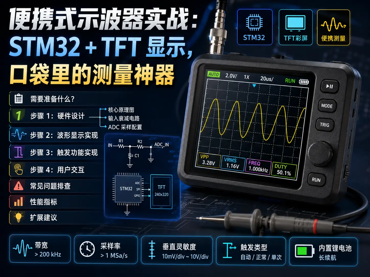
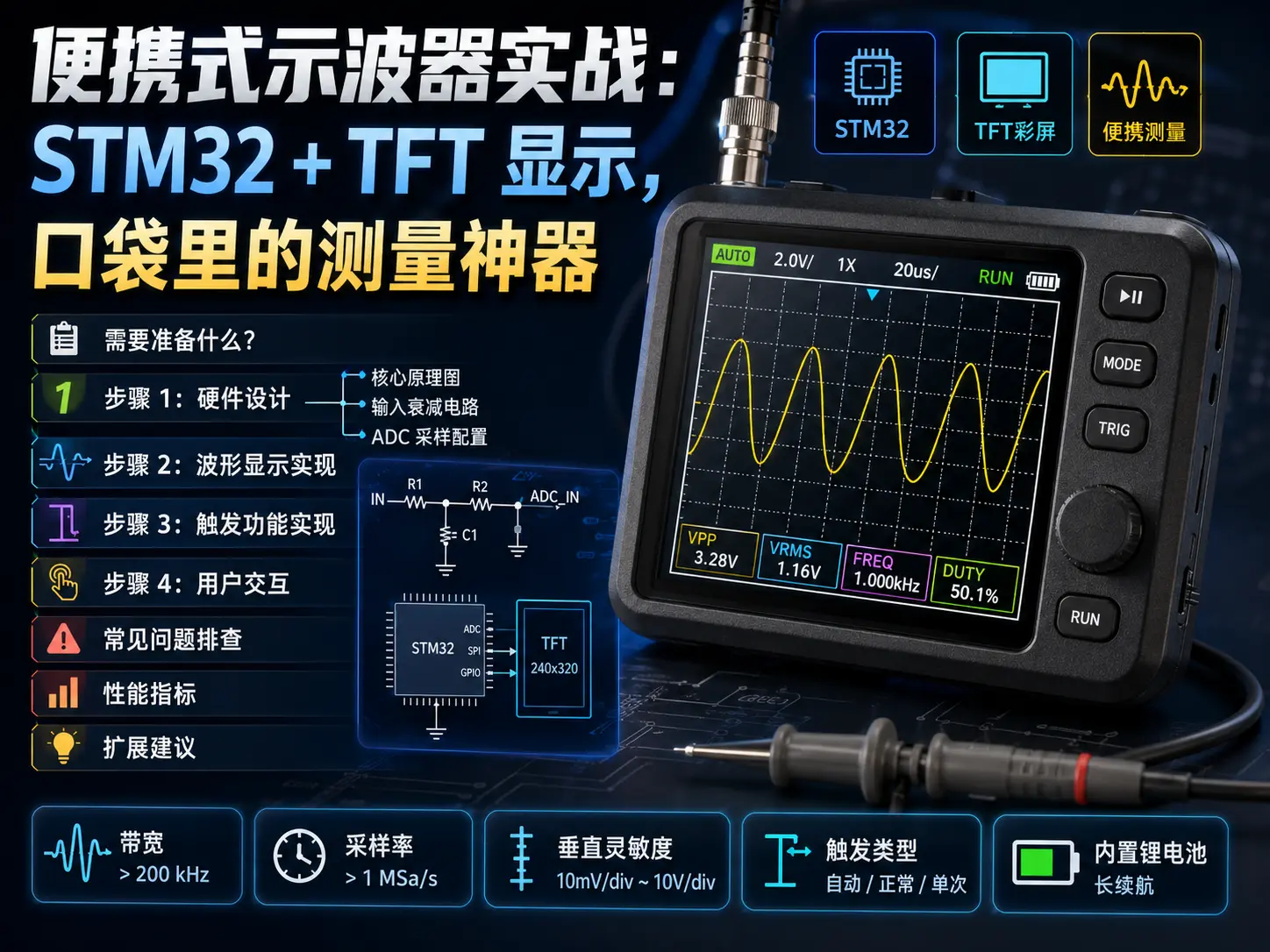
 Portable Oscilloscope in Practice: STM32 + TFT Display, Measurement Tool in Your Pocket
As an embedded engineer, the oscilloscope is definitely one of the most frequently used tools. But desktop oscilloscopes cost thousands or tens of thousands, and they’re bulky. Today we’ll DIY a portable oscilloscope, using STM32 as the main controller, paired with a TFT color screen, costing less than 200 yuan, but able to handle 80% of daily measurement needs.
This project came from a mistake I made: once while debugging a circuit at a client’s site, I found a signal problem but didn’t bring an oscilloscope. By the time I borrowed equipment, the problem couldn’t be reproduced anymore. From then on, I decided to build a small oscilloscope that could fit in my tool bag.
What Do You Need?
| Item | Model/Spec | Price |
|---|---|---|
| Main Controller Board | STM32F407VET6 (168MHz) | ¥45 |
| Display Screen | 3.5-inch TFT LCD (320x480) | ¥35 |
| ADC Module | External 12-bit ADC (optional) | ¥25 |
| Attenuation Circuit | Resistor voltage divider + op-amp | ¥15 |
| Battery | 18650 lithium battery 2000mAh | ¥20 |
| Charging Module | TP4056 charging board | ¥5 |
| Enclosure | 3D printed or acrylic | ¥30 |
| Buttons | Tactile switches x6 | ¥5 |
| BNC Connector | Oscilloscope standard connector | ¥8 |
| Total | ¥188 |
If you have an STM32 development board on hand (like Zhengdian Atom, Wildfire), the cost can be even lower. You can also use a cheaper 2.4-inch display, depending on your needs.
Step 1: Hardware Design
Core Schematic
The oscilloscope has three main tasks: signal acquisition, data processing, waveform display.
Signal Input → Attenuation/Amplification → ADC Acquisition → STM32 Processing → TFT Display
                      ↓                          ↓
                 Range Switching            DMA Transfer
Input Attenuation Circuit
STM32F4’s ADC input range is 0-3.3V, but the signals we want to measure might be 0-20V or even higher. So we need an attenuation circuit:
// Voltage divider resistor calculation: R1=30k, R2=10k → attenuation ratio 4:1
// Input 0-20V → ADC sees 0-5V (then add clamping protection to 3.3V)

void configure_attenuation() {
    // Use analog switch to switch different attenuation ratios
    // 1X: 0-3.3V range
    // 10X: 0-33V range
    HAL_GPIO_WritePin(ATTEN_GPIO, ATTEN_PIN, GPIO_PIN_SET);
}
⚠️ Pitfall reminder: I didn’t add clamping diodes at first, and once accidentally measured 12V, directly burning the ADC pin. Later I added two BAT54S for clamping, much safer.
ADC Sampling Configuration
STM32F407 has 3 built-in 12-bit ADCs, maximum sampling rate 2.4MSPS. We use timer trigger + DMA transfer to achieve continuous sampling:
// main.c - ADC configuration
ADC_HandleTypeDef hadc1;
DMA_HandleTypeDef hdma_adc1;

void MX_ADC1_Init(void) {
    ADC_ChannelConfTypeDef sConfig = {0};

    hadc1.Instance = ADC1;
    hadc1.Init.ClockPrescaler = ADC_CLOCK_SYNC_PCLK_DIV4; // 42MHz
    hadc1.Init.Resolution = ADC_RESOLUTION_12B;
    hadc1.Init.ScanConvMode = DISABLE;
    hadc1.Init.ContinuousConvMode = ENABLE;  // Continuous mode
    hadc1.Init.DiscontinuousConvMode = DISABLE;
    hadc1.Init.ExternalTrigConvEdge = ADC_EXTERNALTRIGCONVEDGE_NONE;
    hadc1.Init.DataAlign = ADC_DATAALIGN_RIGHT;
    hadc1.Init.NbrOfConversion = 1;
    hadc1.Init.DMAContinuousRequests = ENABLE;  // DMA continuous requests
    hadc1.Init.EOCSelection = ADC_EOC_SINGLE_CONV;

    if (HAL_ADC_Init(&hadc1) != HAL_OK) {
        Error_Handler();
    }

    // Configure channel: PA1 (ADC1_IN1)
    sConfig.Channel = ADC_CHANNEL_1;
    sConfig.Rank = 1;
    sConfig.SamplingTime = ADC_SAMPLETIME_3CYCLES;  // Fastest sampling
    if (HAL_ADC_ConfigChannel(&hadc1, &sConfig) != HAL_OK) {
        Error_Handler();
    }
}

// DMA configuration: transfer to buffer
#define ADC_BUFFER_SIZE 1024
uint32_t adc_buffer[ADC_BUFFER_SIZE];

void MX_DMA_Init(void) {
    hdma_adc1.Instance = DMA2_Stream0;
    hdma_adc1.Init.Channel = DMA_CHANNEL_0;
    hdma_adc1.Init.Direction = DMA_PERIPH_TO_MEMORY;
    hdma_adc1.Init.PeriphInc = DMA_PINC_DISABLE;
    hdma_adc1.Init.MemInc = DMA_MINC_ENABLE;
    hdma_adc1.Init.Mode = DMA_CIRCULAR;  // Circular mode
    hdma_adc1.Init.Priority = DMA_PRIORITY_HIGH;
    hdma_adc1.Init.FIFOMode = DMA_FIFOMODE_DISABLE;

    if (HAL_DMA_Init(&hdma_adc1) != HAL_OK) {
        Error_Handler();
    }

    __HAL_LINKDMA(&hadc1, DMA_Handle, hdma_adc1);
}
Start sampling:
// Start ADC acquisition (DMA automatic transfer)
HAL_ADC_Start_DMA(&hadc1, (uint32_t*)adc_buffer, ADC_BUFFER_SIZE);
Step 2: Waveform Display Implementation
We use SPI interface to drive the TFT screen, refresh rate can reach over 30fps. The core of the display part is drawing the ADC sampled data points on the screen:
// display.c - Waveform drawing
#include "lcd.h"
#include "gui.h"

#define SCREEN_WIDTH 320
#define SCREEN_HEIGHT 480
#define WAVEFORM_COLOR 0x001F  // Blue
#define GRID_COLOR 0x8430      // Gray

void draw_grid(void) {
    // Draw grid lines
    GUI_SetColor(GRID_COLOR);

    // Vertical lines (time scale)
    for (int i = 0; i < SCREEN_WIDTH; i += 40) {
        GUI_DrawLine(i, 0, i, SCREEN_HEIGHT);
    }

    // Horizontal lines (voltage scale)
    for (int i = 0; i < SCREEN_HEIGHT; i += 40) {
        GUI_DrawLine(0, i, SCREEN_WIDTH, i);
    }
}

void draw_waveform(uint32_t* data, uint16_t length) {
    GUI_SetColor(WAVEFORM_COLOR);

    int last_y = -1;
    for (int i = 0; i < SCREEN_WIDTH && i < length; i++) {
        // Convert ADC value to screen Y coordinate
        int y = SCREEN_HEIGHT - 20 - (data[i] * (SCREEN_HEIGHT - 40) / 4095);

        // Boundary check
        if (y < 20) y = 20;
        if (y > SCREEN_HEIGHT - 20) y = SCREEN_HEIGHT - 20;

        // Draw line segment (anti-aliasing can be optimized later)
        if (last_y >= 0) {
            GUI_DrawLine(i, last_y, i, y);
        }
        last_y = y;
    }
}

void update_display(void) {
    // Clear screen
    GUI_Clear(0x0000);  // Black background

    // Draw grid
    draw_grid();

    // Draw waveform
    draw_waveform(adc_buffer, ADC_BUFFER_SIZE);

    // Display parameters
    GUI_ShowString(10, 10, "CH1: 5V/div", 12, 0xFFFF);
    GUI_ShowString(10, 25, "Time: 1ms/div", 12, 0xFFFF);

    // Refresh screen
    LCD_Refresh();
}
Step 3: Trigger Function Implementation
An oscilloscope without trigger is like a camera without focus—you can’t see the waveform clearly. We implement a simple edge trigger:
// trigger.c - Trigger control
typedef enum {
    TRIG_MODE_AUTO,
    TRIG_MODE_NORMAL,
    TRIG_MODE_SINGLE
} TrigMode_t;

typedef enum {
    TRIG_EDGE_RISING,
    TRIG_EDGE_FALLING
} TrigEdge_t;

typedef struct {
    TrigMode_t mode;
    TrigEdge_t edge;
    uint16_t level;  // Trigger level (0-4095)
    uint16_t timeout_ms;
} TriggerConfig_t;

TriggerConfig_t trig_config = {
    .mode = TRIG_MODE_AUTO,
    .edge = TRIG_EDGE_RISING,
    .level = 2048,  // Middle voltage level
    .timeout_ms = 100
};

// Detect trigger point
int find_trigger_point(uint32_t* buffer, uint16_t length) {
    for (int i = 1; i < length - 1; i++) {
        uint16_t curr = buffer[i] & 0xFFF;
        uint16_t next = buffer[i + 1] & 0xFFF;

        if (trig_config.edge == TRIG_EDGE_RISING) {
            // Rising edge
            if (curr < trig_config.level && next >= trig_config.level) {
                return i;
            }
        } else {
            // Falling edge
            if (curr >= trig_config.level && next < trig_config.level) {
                return i;
            }
        }
    }
    return -1;  // No trigger point found
}

void trigger_handler(void) {
    static uint32_t last_trig_time = 0;

    int trig_point = find_trigger_point(adc_buffer, ADC_BUFFER_SIZE);
    if (trig_point >= 0) {
        // Found trigger point, update display
        update_display();
        last_trig_time = HAL_GetTick();
    } else {
        // In auto mode, force refresh after timeout
        if (trig_config.mode == TRIG_MODE_AUTO) {
            if (HAL_GetTick() - last_trig_time > trig_config.timeout_ms) {
                update_display();
                last_trig_time = HAL_GetTick();
            }
        }
    }
}
Step 4: User Interaction
Use 6 buttons for basic control:
// buttons.c - Button control
// Button definitions: UP, DOWN, LEFT, RIGHT, ENTER, BACK

void button_handler(uint8_t btn_id, ButtonEvent_t event) {
    static uint8_t menu_selection = 0;

    if (event == BUTTON_PRESS_SHORT) {
        switch (btn_id) {
            case BTN_UP:
                // Increase vertical range
                adjust_vertical_scale(1);
                break;
            case BTN_DOWN:
                // Decrease vertical range
                adjust_vertical_scale(-1);
                break;
            case BTN_LEFT:
                // Decrease timebase
                adjust_timebase(-1);
                break;
            case BTN_RIGHT:
                // Increase timebase
                adjust_timebase(1);
                break;
            case BTN_ENTER:
                // Toggle trigger mode
                toggle_trigger_mode();
                break;
            case BTN_BACK:
                // Return to menu
                show_menu();
                break;
        }
    }
}
Common Problem Troubleshooting
Problem 1: Waveform display unstable, always shaking
- Cause: Improper trigger settings or too much signal noise
- Solution:
- Check if trigger level is within signal amplitude range
- Try switching trigger edge (rising/falling)
- Add 100nF capacitor at input for filtering
- For low-frequency signals, use auto trigger mode
Problem 2: High-frequency signal display distorted
- Cause: Sampling rate not enough or bandwidth limitation
- Solution:
- Decrease timebase (increase sampling rate)
- Check ADC sampling time configuration (use 3 cycles for fastest)
- Confirm signal frequency doesn’t exceed Nyquist frequency (sampling rate/2)
- STM32F4’s ADC maximum 2.4MSPS, theoretical bandwidth 1.2MHz, practical recommendation to measure within 500kHz
Problem 3: Screen refresh too slow
- Cause: SPI clock too low or drawing algorithm inefficient
- Solution:
- Increase SPI clock (maximum 42MHz)
- Use DMA to transfer display data
- Only refresh changed areas (partial refresh)
- Reduce waveform points (use decimation algorithm)
Problem 4: Measurement values inaccurate
- Cause: ADC reference voltage drift or voltage divider resistor error
- Solution:
- Calibrate input voltage with precision multimeter
- Add calibration coefficient in software
- Use external reference voltage source (like REF3033)
- Select 1% precision resistors for voltage divider network
Performance Specifications
Actual measured data after completion:
| Parameter | Specification |
|---|---|
| Bandwidth | DC ~ 500kHz (-3dB) |
| Sampling Rate | Maximum 2MSPS |
| Vertical Resolution | 12-bit (4096 levels) |
| Vertical Range | 1V/div ~ 10V/div |
| Timebase Range | 10μs/div ~ 1s/div |
| Input Impedance | 1MΩ (parallel 20pF) |
| Maximum Input | ±35V (DC+AC) |
| Screen Refresh | 30fps |
| Battery Life | About 4 hours |
This performance is sufficient for digital circuit debugging, sensor signal analysis, and power supply ripple measurement. Of course, compared to desktop oscilloscopes costing thousands, there’s still a gap, but considering the price is less than 1/10, the cost-performance ratio is still very good.
Extension Suggestions
If you want to continue upgrading this project:
- Add second channel - Use STM32’s second ADC, achieve dual-trace display
- Add FFT function - Use DSP library for spectrum analysis
- Support USB drive storage - Save waveform data in CSV format
- Bluetooth/WiFi connection - Mobile APP remote waveform viewing
- Automatic measurement - Frequency, period, peak-to-peak, duty cycle and other parameters
- Lissajous figures - X-Y mode to observe phase relationships
I’ve put the code on GitHub, welcome to star and PR:
- Project address: https://github.com/makeronsite/stm32-oscilloscope
- Schematic/PCB: KiCad project files
- Firmware: STM32CubeIDE project
Summary
From design to debugging, this portable oscilloscope took me about two weekends. The biggest harvest wasn’t how much money I saved, but truly understanding how an oscilloscope works. When using a desktop oscilloscope before, concepts like trigger, sampling, and bandwidth were all abstract. Now after implementing it myself, everything suddenly became clear.
For engineers who often work in the field, or students with limited budgets, this project is very worth trying. Even if you don’t buy the components, just reading the code to learn about ADC, DMA, timer and other peripheral usage is also good practice.
Final reminder: when measuring high-voltage signals, safety must be observed! This oscilloscope’s input is floating ground, cannot directly measure mains electricity. If you need to measure 220V, please use with an isolation transformer or high-voltage differential probe.
Hope this blog article is helpful to you!
Related resources: